Design Features of Fuse Cutouts
The compact lightweight construction of the cutouts ensures complete ease of installation. Each unit is secured by a single bolt fixing at centre mounting point. An adjustable support bracket complete with bolts , nuts and washer is available on request and suitable for cross arm pole of wall mounting.
Insulation level for a given system voltage can vary considerably with climatic and environmental conditions. The availability of both single and double insulator style of cutouts can therefore provide and optimum choice in the selection of most suitable design
The active components of cutouts are common in design and have following features :-
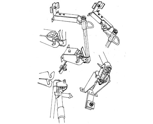
- The fuse carrier drops down when the fuse element melts providing positive fault isolation and a clear indication that the cutout has operated
- The operating ring will accommodate most standard operating pole heads thus allowing the cutouts to be integrated into the system without the need for additional line operating equipment
- Installation and removal of fuse carrier is achieved by positive engagement of the operating pole head onto a pick up tongue positioned at the hinge end of the expulsion tube
- The fuse carrier is designed to accommodate standard expulsion Fuse Links of the button head pattern. Two speeds of operation are available :- Type K ( Fast operating ) and Type T ( Slow operating ) each with rating for 1 to amperes
- A spring loaded flipper and locking mechanism at the lower end of the fuse carrier ensured consistent tension on the fuse link and prevents element damage during close in. The flipper also assists rapid withdrawal of the fuse link from the tube under low fault conditions
- Current transfer is via high pressure silver plated contacts and is completely independent of the lower support hinge The lower contact arrangement ensures positive seating at the hinge point and limits degree of misalignment during close in It also assists the initial opening movement of the fuse carrier when operating
- The expendable cap design provides double venting during high fault current interruptions and single venting under low fault conditions Replacement diaphragms are supplied with each pack of fuse links
- The galvanized steel hood protects the top contact assembly from contamination and guides the fuse carrier into its correct latching position during close in
- Each cutout is supplied complete with connector terminals suitable for conductor sizes ranging from 4 to 10 mm diameter
NOTE:
Other sizes available on request
All dimensions in mm / inches * We reserve the right to change design & construction without prior notice